Lesson Plans
Return to Lesson Plan Index
Printer Friendly Version
Mechanical Properties of 3D Printed Parts in Fused Deposition Modeling
Grades: 9-12
Author: Todd Alkire
Source: Original - This material is based upon work supported by the National Science Foundation under Grant No. EEC- 1542358.
Abstract
Today’s students are not aware of the many uses of polymers in their daily life. In this experiment, students will examine the mechanical properties of 3D parts to solve a real world problem. Students will determine the optimal mechanical properties of components fabricated with 3D printers. Students will create 3D printed parts with various print specifications such as orientation, temperature, infill, layer thickness, etc. This research, testing and analysis will then be used by the students to create a DIY assistive technology (DIY-AT), “which is any device or system that allows an individual to perform a task that they would otherwise be unable to do, or increases the ease and safety with which the task can be performed” [1]. Once the students have created their 3D printed parts, they will conduct a tensile test. The data collected will be graphed and analyzed with the conclusion of the experiment to be a collaborative discussion of the Students will use data gathered from the tensile testing to determine optimal properties for use in assistive technology.
[1] Cowen,D. & Turner-Smith,A. The role of assistive technology in alternative models of care for older people. In Sutherland,I. (ed.) With Respect To Old Age:The Royal Commission for the Long Term Care of the Elderly (1999), Stationary Office, 325-346
Objectives
What should students know as a result of this lesson?
- The students will comprehend the many uses of polymers in their daily lives.
- The students will identify the optimal properties of the 3D printed parts.
- The students will understand how various print specifications affect the strength and usability of 3D printed parts.
- The students will explain orientation, temperature, infill, and layer thickness among other print specifications.
What should the students be able to do as a result of this lesson?
- Students will research various print specifications associated with 3D printing.
- Students will hypothesize the effects of changing the print specifications on 3D printed parts.
- Students will design a controlled experiment testing the tensile strength of their 3D printed part.
- Students will cite evidence collaboratively to determine the optimal material for use in assistive technology.
Materials
- Desktop Computer, 3D Printer(s)
- CAD software, 3D printing software
- 3D printed test specimens
Testing Apparatus
- 5 gallon bucket
- 1 plated steel U bolt
- Quick link-stainless steel (easily found at Home Depot)
- Two flat structures to create a span (this could be tables, etc)
- Sand, weights, etc. to apply load
- Bathroom scale
Procedures
Engagement Part 1: Checking Student’s Past Knowledge of Polymers
- Teacher will ask students to make a list with their partner of polymers they come into contact with in a day. Students are not to use their phones or electronic devices.
- Teacher will then ask the students to report out (expecting answers like plastic water bottles, pens, computers, baggies, etc) Teacher will then point out some of the less obvious polymers that students that they come in contact with daily.
- Teacher will take this opportunity to "define" a polymer.
- Students will then have the opportunity to "play" with polymers (this is teacher's' choice-silly putty, diaper magician, etc)
Engagement Part 2: Real Life Example of Polymers Used for Service
- Teacher will lead a discussion with the students explaining the application of polymers in additive manufacturing.
- Teacher will then narrow that discussion by showing a video on fused deposition modeling. https://www.youtube.com/watch?v=WHO6G67GJbM
- Teacher will then demonstrate actual 3D printing in operation. Students will be able to walk around the lab and watch the printing as well as handle the parts produced.
- Teacher will play a video on prosthetics. https://www.youtube.com/watch?v=3ZyDLGgSj60
- Teacher will discuss with the students that the goal of this lesson is to use their knowledge for service. Teacher will explain what assistive technology is and how it will relate to this lesson. "Our typical mechanical projects are not necessarily impactful on the world." "Now that you have seen this video you can see how easy it would be for us to help".
- Teacher will direct students to a think-pair-share brainstorming different uses of polymers for assistive technology. (expected answers are to align with the definition of AT). If there is time remaining students will report out their list.
Exploration Part 1: Create the part in Computer Aided Design (CAD) software
The use of Computer Aided Design (CAD) software must be used to create the part file to eventually be tested. Software such as SolidWorks and Autodesk Inventor are common but can be costly for a normal classroom environment. OpenSource programs such as OpenScad, FreeCAD, and Google SketchUp are free, easy to learn, and will be more than sufficient for this project. This procedure assumes students have access to and are fluent in some sort of CAD software.
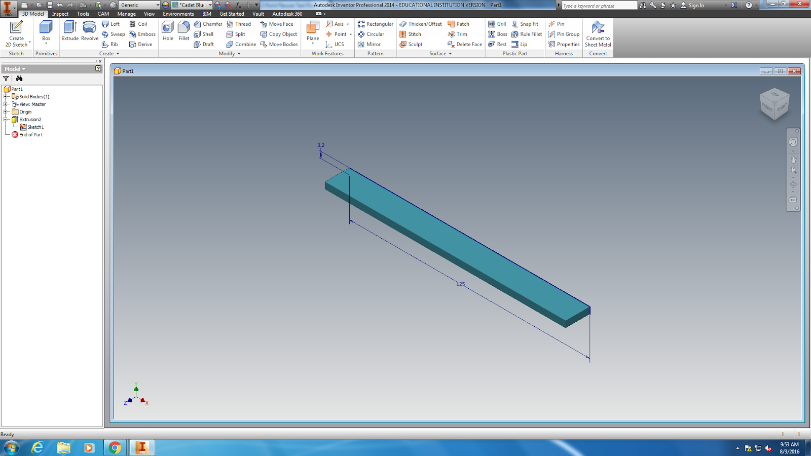
- Create the test specimen in the shape of a rectangular object to fit within ASTM International standards. Though a variety of specimen shapes can be used for this test, the most commonly used specimen size for ASTM is 3.2mm x 12.7mm x 125mm (0.125" x 0.5" x 5.0").
- ASTM International is an international standards organization that develops and publishes technical standards for a wide range of materials, products, systems, and services.
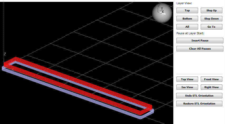
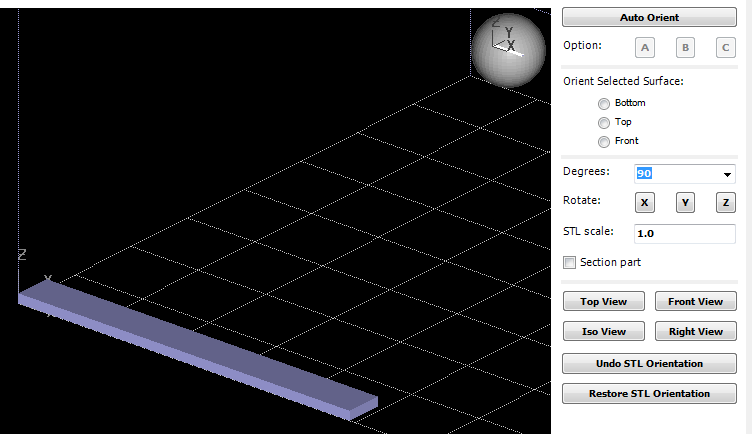
- Once the part has been created and properly saved, convert the CAD file into an STL file. (STL is a standard file type used by most additive manufacturing systems)
- Step-by-step instructions for converting CAD files to STL can be found on most CAD software company’s websites or various user forums.
- The example below is specific to Autodesk Inventor.
- Select IPro > Print > 3D Print Preview
- Select Options and choose desired resolution and click OK
- Within the preview window, select Save Copy As or Send to 3D Print Service
- Save As type to STL File (*.stl)
- Now it’s time to head to the 3D printer. All 3D printers use slicing software to prepare or "slice" the STL file into g-code that the printer can understand. Most commercial printers use some sort of proprietary software specific to their machine. (Though there are several Open Source options such as Cura, Repetier, and Slic3r.) In this example we will use Catalyst EX.
Exploration Part 2: Strength Test Procedure of 3D Printed Filament
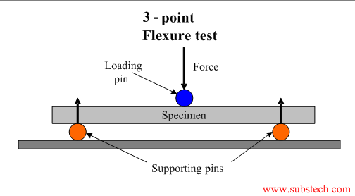
In engineering, flexure or bending describes the behavior of a structural element subjected to an external load. The load is applied perpendicular to the longitudinal axis of the test specimen. In this experiment we will conduct a destructive test to determine the maximum weight capacity of the printed test beam. Essentially adding weight until the part breaks.
Materials:
- 3D printed test specimens
Testing Apparatus:
- 5 gallon bucket
- 1 plated steel U bolt
- Quick link-stainless steel (easily found at Home Depot)
- Two flat structures to create a span (this could be tables, etc)
- Sand, weights, etc. to apply load
- Bathroom scale
Testing the Part:
- Pass the test beam through the U bolt so the plate rests on top of the test beam.
- Carefully place the test beam across two chairs or tables of the same height as shown in Figure 1
- Adjust the test beam across the span so the ends of the beam are supported equally.
- Ensure the bucket is hanging straight down from the center of the test beam.
- 3. Add sand/weights to the bucket.
- If conducting a pass/fail test, premeasure the sand before adding it to the bucket.
- If conducting a destructive test, continue to gradually add sand until the structure breaks, then measure the weight of the sand.
- Record data in engineering notebooks.
Explanation
Teams will share the results of their experiment by creating a poster to include the following items. The poster is to be 24" x 24" and include the following items.
- Title & Names of team members
- Introduction: In one or two paragraphs, provide an introduction and background about the project. Include a statement of the problem presented, the criteria for the design, and the primary objective.
- Procedures: Discuss experiment design, variables and procedures. Provide sketch/photo(s) of the design and testing process. Discuss any plan changes or difficulties you encountered during the testing process.
- Data Charts and Graphs: Charts and graphs will thoroughly represent all trials, be properly labeled and neat.
- Summary of the Test Results: In one or two paragraphs provide a detailed analysis and conclusion of the experimental outcomes. Describe the physical characteristics of the test beam after the applied load and implications of those characteristics.
Elaboration
- Students will derive optimal print specifications for use in assistive technology.
- Students will use the knowledge they have gained about polymers and 3D printing to think of ways in which 3D printing can be used to create assistive devices that can be easily printed and aid others in their daily lives.
Prerequisites
Students will need previous experience with some sort of CAD software. For the inexperienced user most software websites have extensive videos/tutorials to create the test specimens for this activity. The level of CAD knowledge necessary is relatively basic.
Best Teaching Practices
- Inquiry Approaches
- Real Life Situations and Problem Solving
- Hands On / Minds On Learning
- Learning Cycle
Alignment with Standards
NGSS Standards:
- HS-ETS1-2 Design a solution to a complex real-world problem by breaking it down into smaller, more manageable problems that can be solved through engineering.
Ohio Standards:
Ohio Career Field Content Standards
Strand 5. Pre-Engineering: Design and Development Learners apply principles of design and development related to the design process, sketching and visualization, modeling, drafting, materials and production and process design.
- Outcome 5.1. The Design Process - Use the engineering design process and quality assurance principles to analyze and solve design problems.
- Outcome 5.3. Computer-Aided Modeling - Create models to illustrate the design of projects and components.
- Outcome 5.5. Materials - Select materials for design projects and components.
Content Knowledge
N/A
Safety
- The hot ends, print beds and printed parts of a 3D printer reach extreme temperatures that can result in burns. Use appropriate gloves and eye protection.
- Eye protection is required for the flexure test in the event small pieces of the test part may break off
- Closed toe/heel shoes
- Lifting hazard. Lift/carry the weighted bucket with caution to prevent injury
Applications
Polymeric materials such as plastics are used in a wide variety of items on a daily basis and many of these materials are being used in structural capacity. It is important to understand the mechanical properties of these materials for the proper application.
The use of assistive technology can be prohibitive for the end user due to cost, generic design, and the complexity of ever changing needs of the individual. The need for DIY-assistive technology is constantly growing.
Assessment
Teams will share the results of their experiment by creating a poster to include the following items. The poster is to be 24" x 24" and include the following items.
- Title & Names of team members
- Introduction: In one or two paragraphs, provide an introduction and background about the project. Include a statement of the problem presented, the criteria for the design, and the primary objective.
- Procedures: Discuss experiment design, variables and procedures. Provide sketch/photo(s) of the design and testing process. Discuss any plan changes or difficulties you encountered during the testing process.
- Data Charts and Graphs: Charts and graphs will thoroughly represent all trials, be properly labeled and neat.
- Summary of the Test Results: In one or two paragraphs provide a detailed analysis and conclusion of the experimental outcomes. Describe the physical characteristics of the test beam after the applied load and implications of those characteristics.
Other Considerations
Grouping Suggestions: Groups of no more than 2-3 students is suggested.
Pacing/Suggested Time: This lesson was written under the assumption of a lack of technical equipment to conduct a true tensile or flexure test. The apparatus as demonstrated cost less than $11. The ability to create stress-strain curves and derive the modulus of the specimen can be conducted with commercially made equipment and software from companies such as Vernier, PASCO, Pitsco and AMT Stress Analyzer 1000. This project can easily stretch into weeks if necessary. To save time one can omit the CAD lesson and print all the test specimens prior and focus only on the strength test.
Printable PDF Worksheets
Safety Disclaimer